Star Delta Starter
During
this self starting period, as torque increases, a large amount of current flows
in the rotor. To achieve this the stator draws a large amount of current and by
the time the motor reaches its full speed, a large amount of current is drawn
and coils get heated up, damaging the motor. Hence there is a need to
control the motor starting. One way is to reduce the applied voltage, which in
turn reduces the torque.
Objectives of Star-Delta Technique Motor Starter
are:
- Reduce
high starting current and along these lines forestall motor from
overheating
- Provide
over-burden and no-voltage assurance
Star Delta Starter:
In star delta starting, the motor is connected in STAR mode
throughout the starting period. When the motor reached the required speed, the
motor is connected in DELTA mode.
Components of a Star-Delta Starter:
Contactors:
The
Star- Delta starter circuit comprises of three contactors: Main, star and delta
contactors. The three contactors are solicited to unite the motor windings
first in star and afterward in delta.
Timer:
The contactors are regulated by a timer
incorporated with the started.
Interlock switches:
Interlock switches are connected between star and delta
contactors of the control circuit as a safety measure so one can’t activate delta
contactor without deactivating star contactor. By any chance if star and delta
contactors are actuated at the same time, the motor will be damaged.
Thermal overload relay:
A thermal over-load relay
is likewise consolidated into star-delta control circuit to ensure the motor
from intemperate heat which might expedite motor finding fire or wearing out.
In the event that the temperature goes past a preset quality, the contact is
open and power supply is cut in this manner ensuring the motor.
Working of Star-Delta Starter:
At first the primary
contactor and the star contactors are shut. After a time interval the timer
signs to the star contactor to head off to the open position and the primary,
delta contactors to head off to the shut position, accordingly structuring
delta circuit.
At
the time of starting when the stator windings are star associated, every stator
stage gets voltage VL/√3, where VL is the line voltage. Hence, the line current
drawn by the motor at starting is decreased to one-third as contrasted with
starting current with the windings associated in delta. Likewise, since the
torque advanced by an induction motor is corresponding to the square of the
applied voltage; star- delta starter decreases the starting torque to one-
third of that possible by immediate delta starting.
The timer controls conversion from star
connection to delta connection. A timer in star delta starter for
a 3-phase motor is intended to do the move from star mode, utilizing which the
motor runs on a decreased voltage and current and produces less torque – to the
delta mode indispensible for running the motor at its full power, utilizing
high voltage and current to transform a high torque.
Terminal Connections in Star and Delta
Configurations:
L1,
L2 and L3 are the 3-phase line voltages, which are given to primary contactor.
The main motor coils are U, V and W is shown in figure. In star mode of motor
windings, the primary contactor associate the mains to essential winding
terminals U1, V1 and W1.the star contactor shorts the auxiliary winding
terminals U2, V2 and W2 as indicated in figure. Notwithstanding when the
primary contactor is shut supply arrives at terminals A1, B1, C1 and
consequently the motor windings are energized in star-mode.
The
timer is initiated in the meantime moment when star contactor is energized.
After the timer achieves the specified time period, the star contactor is
de-energized and delta contactor is energized.
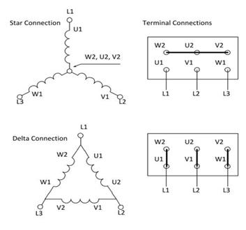
The point when delta contactor closes, the motor winding
terminals U2, V2 and W2 get associated with V1, W1 and U1 individually through
the shut contacts of primary contactor. That is for delta association,
fulfilling end of one winding is to be joined with beginning end of the other
winding. The motor windings are reconfigured in delta by supplying line voltage
L1 to winding terminals W2 and U1, line voltage L2 to winding terminals U2 and
V1; and line voltage L3 to winding terminals V2 and W1, as indicated in figure.


Comments
Post a Comment